I was talking to a family member recently who had one of those atomic clocks which synchronized their time with the MSF radio time signal which is transmitted by the National Physical Laboratory in the UK from the Anthorn Radio Station in Cumbria. You can buy one of these clocks very cheaply from websites such as EBay. This time signal can be received pretty much anywhere in the British Isles. With my interest piqued I wondered if this was something you could develop from scratch using some type of Arduino microcontroller. Please note that there are other international radio time signals available in other parts of the world such as WWVB for North America, JJY in Japan and DCF99 in Germany. Note that this sketch will only operate with the MSF time signal as each station has their own standard for how the time information is transmitted. The specification for the MSF signal details is available on the NPL web site at https://www.npl.co.uk/products-services/time-frequency/msf-radio-time-signal/msf_time_date_code. Basically the specification transmits up to 2 bits of information per second with each bit type being determined by the duration of the signal pulse during that second interval. There is also a Begin of Minute marker used for initial synchronization with the time signal. Then various bits at different seconds encode The current Year, Month, Day of Week, Hour and Minute values. Also encoded in the bits is the current offset between UT1 and UTC, whether British Summer Time is currently active, whether British Summer Time is imminent and some parity bits to check the received information. You can also infer if a leap second was inserted or removed by the presence of a sixtieth second or the absence of a fifty-ninth second.
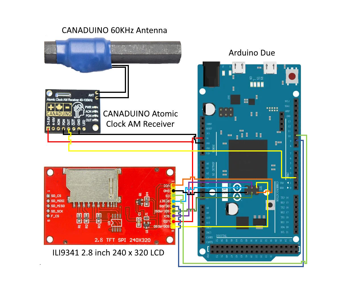
I initially tried using an Arduino Mega 2560 microcontroller, along with an ILI9341 320 x 240 LCD display and a prebuilt receiver / antenna unit called the CANADUINO Atomic Clock AM Receiver unit. I quickly realized that I would not be able to get the LCD display to easily work with the Mega 2560 microcontroller as the LCD display uses 3.3V SPI while the Arduino 2560 microcontroller only does 5V SPI. I could have incorporated 5V to 3V level shifter chips into the circuit but I eventually wanted to mount the circuit in a box with a breadboard with jumper cables directly to the microcontroller, and avoid the need for a PCB for the project. Some research then lead to the Arduino Due microcontroller. This is a much more advanced Arduino than the Mega 2560, with the main difference being that it is ARM based, runs at a much higher frequency and most importantly for me runs at 3.3V instead of 5V.
The sketch depends on the following libraries which you must have installed in your Arduino IDE to compile and upload the sketch if you want to try out the code yourself:
Adafruit RTCLib at https://github.com/adafruit/RTClib: The sketch can optionally use this library to interface with a DS3231 Real Time clock. By default the sketch does not include this library when compiling.
Adafruit GFX library at https://github.com/adafruit/Adafruit-GFX-Library: This is used to provide basic drawing support for the LCD display.
Adafruit ILI9341 library at https://github.com/adafruit/Adafruit_ILI9341: This is used to interface to the LCD display.
Arduino Time Library by Paul Stoffregen at https://github.com/PaulStoffregen/Time: This library provides basic time functionality as a replacement for the need for a Real Time Clock board.
The sketch basically times the duration of the up and down pulses by reading the digital value on PIN 2 from the CANADUINO receiver 50 times separated by 1 millisecond. This value is then averaged to determine if the pulse was present or not present over this 50 millisecond interval. This approach helps reduce issues due to short duration transient noise on the signal. These pulse durations are then built up and compared to the pulse durations included in the MSF signal specification. Because of the way the pulses are averaged and the fact that you only know that you have got the Begin of Minute marker at the 1 second mark plus or minus the 50 millisecond window, you in fact cannot really use the sketch as is for a source of Time Synchronization to the likes of a PC or network device. For that you would need a much more complicated sketch.
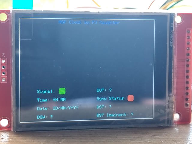
When the sketch is first powered up and before it has received the first Begin of Minute marker, the LCD should appear as below:
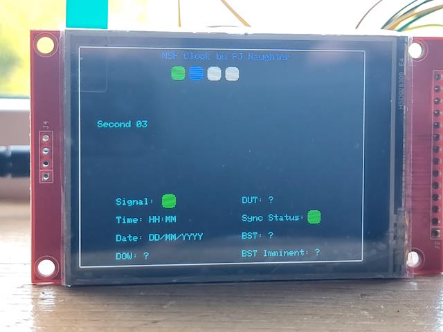
After the first Begin of Minute marker has been received, you will see the LCD display each consecutive second in a 10 x 6 grid of squares as follows:
Then once a full minute of pulses have been received, you will see the full selection of information decoded and displayed as follows:
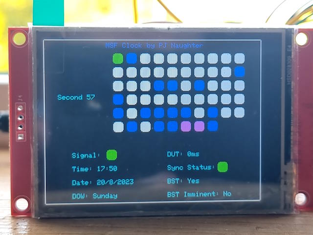
Each second is represented by a square in the 10 x 6 grid of squares. The Begin Of Minute marker is represented by the first green square in the grid. A blue square represents a A=1 and B=0 type second. A white square represents a A=0 and B=0 type second. A Magenta square represents a A=1 and B=1 type second.
The signal value is represented by a green square which blinks on and off in sync with the received signal.
The DUT value is the current difference in milliseconds between UT1 and UTC.
The "Sync Status" is a green square when the clock has synchronized to the signal and will be red when there is currently no synchronization.
The Date value is the DD/MM/YYYY form of the current date.
The BST value is "Yes" if British Daylight Savings is currently in effect and will be "No" otherwise.
The DOW value is the current Day of the Week.
The "BST Imminent" value indicates if time is about to transition into BST in the next hour.
The sketch can also output diagnostic information to the serial port of the microcontroller to aid in debugging the sketch. The LCD display I used for the sketch also supports touch input, but it is not something I wired up. This is something the intrepid reader could extend to support if they want. Another thing to point out is that depending on your distance to the Anthorn transmitter, the signal is quite weak and can be easily overpowered by interference from local electronics such as TV's, Computers or Computer Monitors. To help with this issue I extended the three leads (5V, GND and SIGNAL) from the AM receiver to the Arduino Due using some TRRS cable and two TRRS breakout boards. This helps to keep the antenna and receiver pair away from the microcontroller and your computer when you are debugging the sketch in the Arduino IDE. Due to the use of the more powerful Arduino Due in the project along with the use of a LCD Display, the sketch draws about 180 milliamps. I played around with disabling the serial output in the sketch but this did not reduce the current usage. If I disabled the LCD output in the sketch then the circuit ran at about 150 milliamps but then the sketch is not very useful. If you power this project using a standard 10,000 mAh USB Battery bank, then the project will run for about 50 hours. If you used a 30,000 mAh battery bank, then you should be able to keep it running for just over 6 days. You can of couse just power the Arduino using a mains USB charger. I will leave optimizing this sketch for battery usage to the reader!.
The schematic
for the hardware for the project is as follows:
1.01 (14 October 2023)
1.0 (20 August 2023)